Adding Text to the Layout
Now it's time to start adding text fields to the layout. We begin with the name of the company, XYZ Steel Co. We want this text to appear
at the top of the layout, straddling the hole.
 First, we select the Text tool from the toolbar on the left side of the
Designer. Once the tool is selected, we click on the layout in the location that will be the lower left corner of the text. While continuing to hold
down the mouse button, drag the mouse pointer up and to the "right" (remember our tag image is rotated 90 degrees) to size the text. First, we select the Text tool from the toolbar on the left side of the
Designer. Once the tool is selected, we click on the layout in the location that will be the lower left corner of the text. While continuing to hold
down the mouse button, drag the mouse pointer up and to the "right" (remember our tag image is rotated 90 degrees) to size the text.
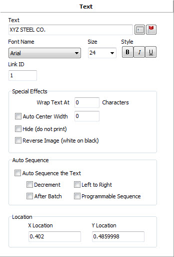
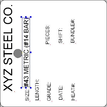
When we release the mouse button, the properties editor will show the configuration of the Text field. This editor allows us to specify the text
to print along with other properties that affect its appearance. Enter "XYZ STEEL CO." into the Text field and click the Enter key. We
will keep the default font of "Arial" and size of 24 (which was determined automatically for us based on the size of the stretch box we
drew.) The Rotation of 90 degrees was determined for us also, based on the direction that we drew the stretch box (from lower right of the screen to
upper left of the screen.)
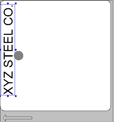
 After entering the text, press the Enter key to save the field. The
layout will be redrawn to show the new field. After entering the text, press the Enter key to save the field. The
layout will be redrawn to show the new field.
You can move the field around using the mouse. Simply click and hold the mouse button anywhere on the
field and drag. When you get it where you want it, release the mouse button and the field will be moved.
To resize the field, click and drag one of
the blue squares located around the selected field.
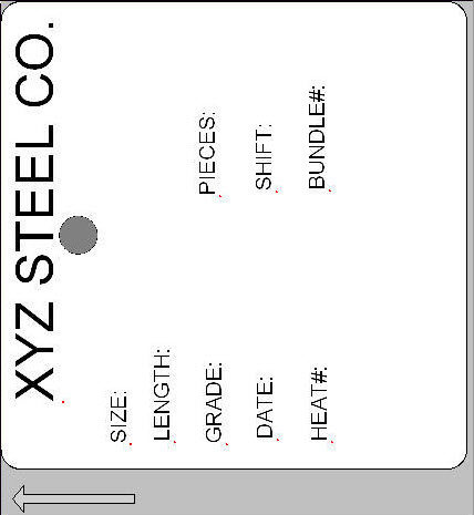
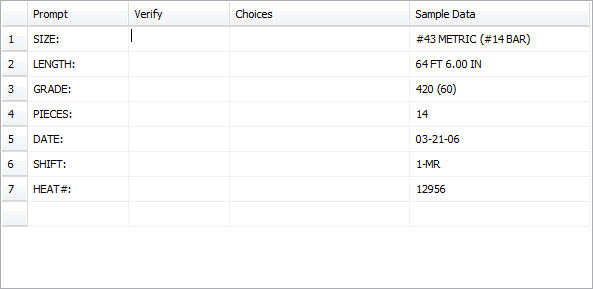
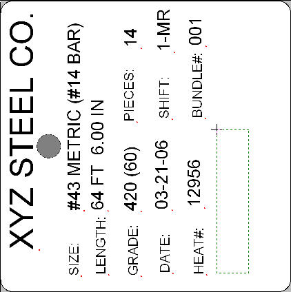
Congratulations, you have just added your first text field to the layout. Now, using the same techniques, add each of the fixed labels
("SIZE:", "LENGTH:", etc.) to the layout. Don't worry too much about placement at this time, since we will be cleaning up the
look of the layout later. Once you have finished, you should have a layout that looks something like this:
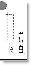
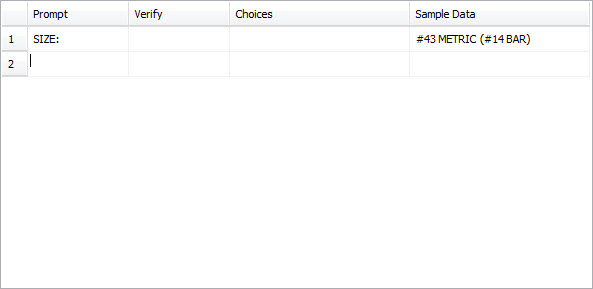
Now that we have our fixed text prompts, the ones that never change, we can begin adding our variable text fields. Remember, we want to link
these variable fields to the Operator Data Entry fields we created earlier. Let's begin with the first field, "SIZE". Select the Text Tool
if it isn't already selected. Draw a stretch box like before, but begin next to the "SIZE:" prompt as shown below.
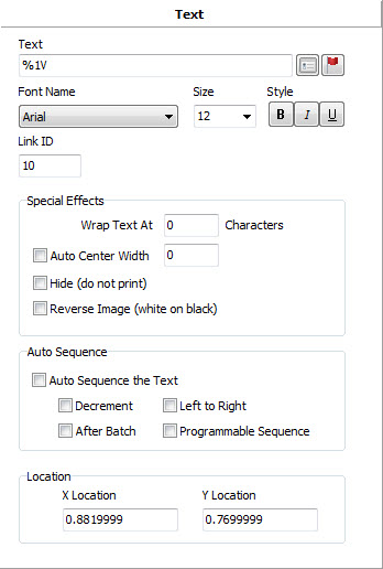
 This will bring up the property editor as shown below. This will bring up the property editor as shown below.
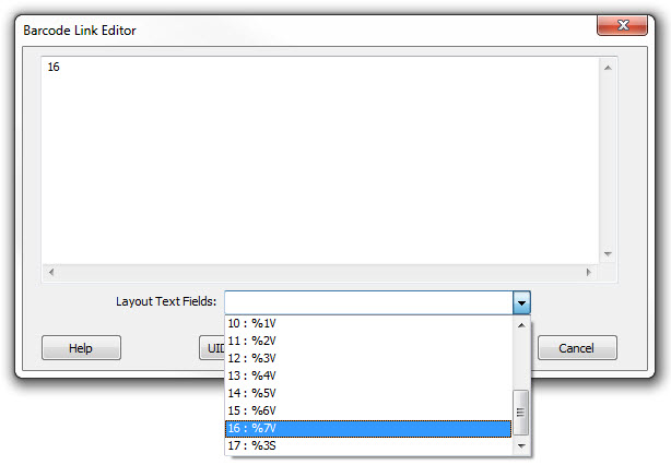
In the Text field,
we need to enter a special "flag" that tells Producer that what you really want to print here is the first of the Operator Data Entry
fields. This flag is "%1V". The percent character tells Producer that what follows is a special "flag" field. The "1V"
indicates the first of the Operator Data Entry fields.
There are many such flags that allow you to insert automatically generated or sequenced data.
 After entering the flag in the Text property and clicking the Enter key,
the tag will be redrawn as shown. After entering the flag in the Text property and clicking the Enter key,
the tag will be redrawn as shown.
Notice how we made the data portion of this field a bigger font than the label that goes with it. This is purely individual preference, but I
feel that it makes it easier to locate the data from the labels.
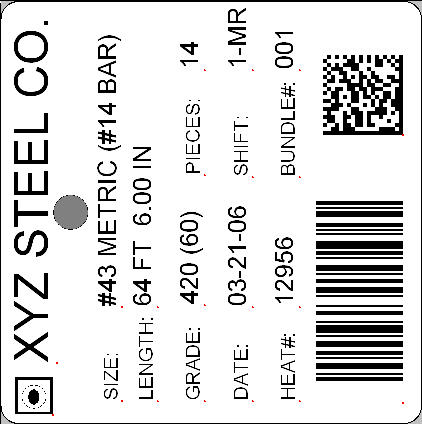
Now go ahead and add the remainder of the variable data fields, except for the "BUNDLE#" since we plan to make that an auto sequencing
field. Remember, that to refer to the second Operator Data Entry field, you would use %2V, and so on. Once your finish, your layout should look
something like this:
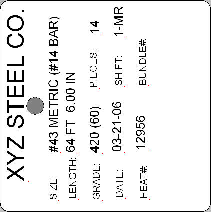 Again, don't be too worried about how the fields line up at this point.
Just get everything placed about where it belongs and we'll clean it up later. Again, don't be too worried about how the fields line up at this point.
Just get everything placed about where it belongs and we'll clean it up later.
|
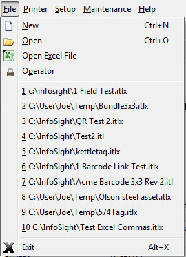 Producer will ask you for the Supervisor Password if
you are not already in the supervisor mode. Once you supply the correct password, Producer will launch the Layout Designer, a separate program. As
soon as the Designer starts, it will show you a list of common tag sizes, materials and colors. Simply select the image that matches your tag
configuration. If your tag does not appear in the list, select the first "blank" layout and customize it manually.
Producer will ask you for the Supervisor Password if
you are not already in the supervisor mode. Once you supply the correct password, Producer will launch the Layout Designer, a separate program. As
soon as the Designer starts, it will show you a list of common tag sizes, materials and colors. Simply select the image that matches your tag
configuration. If your tag does not appear in the list, select the first "blank" layout and customize it manually.
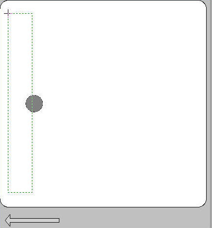
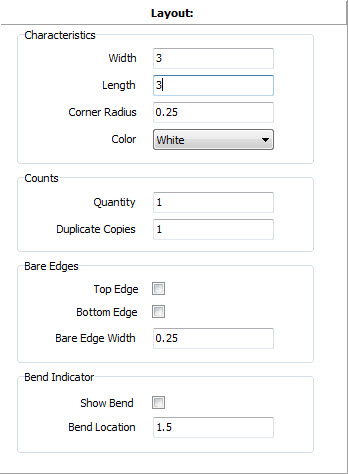 The first two fields in the Layout property editor are Width and
Length. The length dimension is in the direction that the tag material feeds out of the printer as shown by the gray arrow next to the tag image.
The first two fields in the Layout property editor are Width and
Length. The length dimension is in the direction that the tag material feeds out of the printer as shown by the gray arrow next to the tag image.
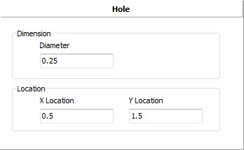 Once you have placed your hole, use the property edit to enter the
hole Diameter and X,Y coordinates of the hole's center location, relative to the lower left corner of the tag.
Once you have placed your hole, use the property edit to enter the
hole Diameter and X,Y coordinates of the hole's center location, relative to the lower left corner of the tag.
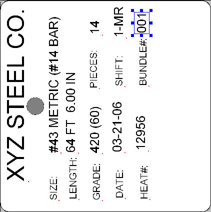
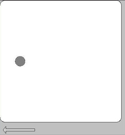 Notice the arrow that indicates the direction of feed. This shows that
the side of the tag with the hole will feed out of the printer first. We can consider this the top of the tag because we want the text to flow under
the hole since the tag will be hanging from a wire that passes through the hole. Because of this, we will have to orient our fields at 90 degrees
rotation as we will discuss later.
Notice the arrow that indicates the direction of feed. This shows that
the side of the tag with the hole will feed out of the printer first. We can consider this the top of the tag because we want the text to flow under
the hole since the tag will be hanging from a wire that passes through the hole. Because of this, we will have to orient our fields at 90 degrees
rotation as we will discuss later.
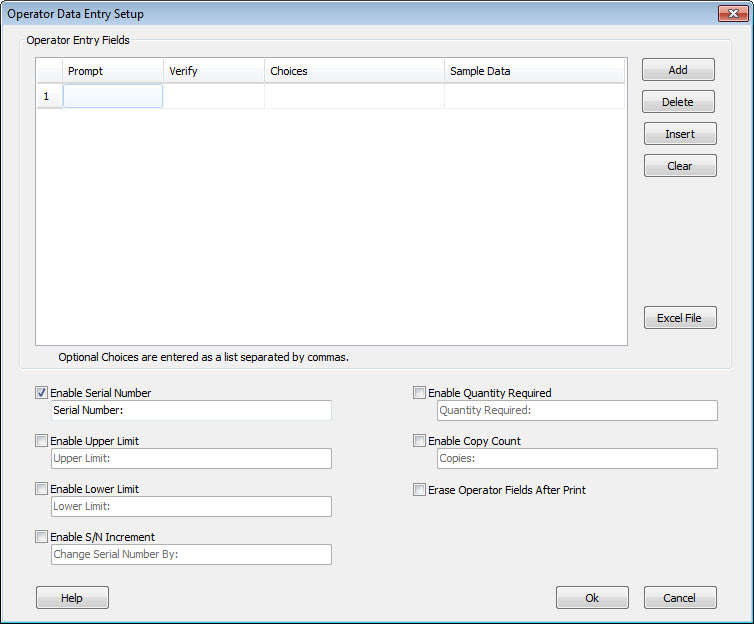
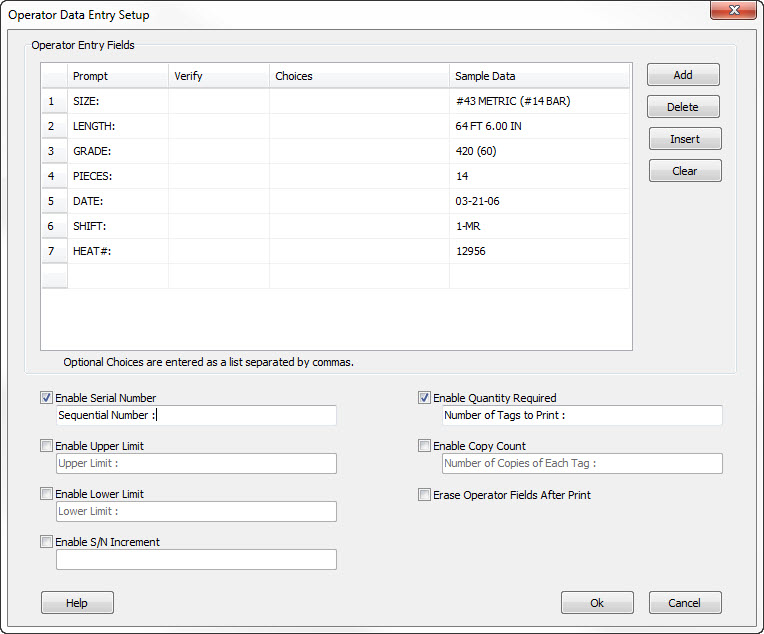
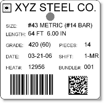
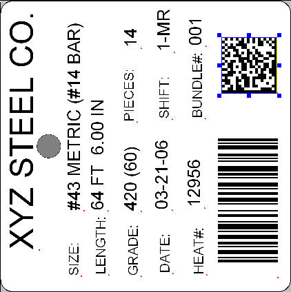
 As you can see here, the layout now contains a three digit serial number
starting with 001. We have allowed the operator to specify the starting serial number by check the box "Enable Serial Number" in the
Operator Data Entry configuration screen. As each tag is printed, the serial number will increment by one (the default.)
As you can see here, the layout now contains a three digit serial number
starting with 001. We have allowed the operator to specify the starting serial number by check the box "Enable Serial Number" in the
Operator Data Entry configuration screen. As each tag is printed, the serial number will increment by one (the default.)
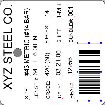
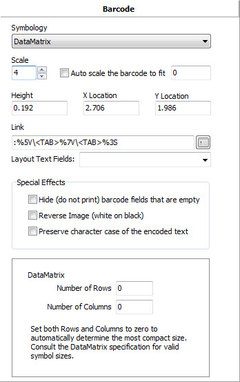
 When you release the mouse button, the property editor will show the
properties of this Barcode field. In this editor, you must specify the barcode symbology, scale and link. For our example we are going to use the
Code128 type of barcode. We chose scale 4 (X dimension is 4 pixels wide.)
When you release the mouse button, the property editor will show the
properties of this Barcode field. In this editor, you must specify the barcode symbology, scale and link. For our example we are going to use the
Code128 type of barcode. We chose scale 4 (X dimension is 4 pixels wide.)
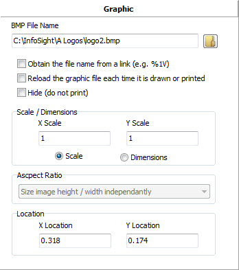 In the File Name field, you may type the complete path to the logo
bitmap file, our you may click on the Browse button and locate it in the File Open dialog.
In the File Name field, you may type the complete path to the logo
bitmap file, our you may click on the Browse button and locate it in the File Open dialog. 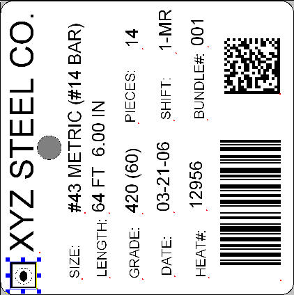
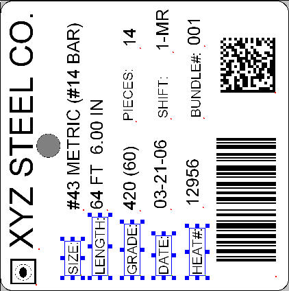
 For the Alignment tools to work, you must first select more than
one field. Do this by clicking on one field, holding down the CTRL key and then clicking on the additional fields you want to select. Each selected
field will have a blue selection box around it.
For the Alignment tools to work, you must first select more than
one field. Do this by clicking on one field, holding down the CTRL key and then clicking on the additional fields you want to select. Each selected
field will have a blue selection box around it. As you can see, I have selected five of the labels that I want to align
on their "bottom" edge. This is not the bottom of the fields themselves, but the bottom of the display.
As you can see, I have selected five of the labels that I want to align
on their "bottom" edge. This is not the bottom of the fields themselves, but the bottom of the display.